| Build Your Own ! |
 Regulator circuit wired into a Box Mod. |
This is an add on to the simple battery case mod. A problem with simple big battery mods is that most lithium batteries you buy from the store are un-regulated. That is, they start off fully charged at around 4.2v and eventually dwindle down to about 2.5v before cutting out. Higher and lower voltages (nominal 3.7v) produce higher and lower currents and can affect the taste from effects like over heating the e-liquid or not enough heat. You can also get a sore tongue or throat from over heated vapour. not to mention shortening the life of an atomiser. So to give a more consistent vape, some manufacturers add what's called a 'regulator' circuit to either the battery or the switcher. These 'regulators' vary in performance. Expensive circuits will boost to the nominal voltage (3.3v ~ 3.7v) if the battery falls below, and limit to this range if the battery starts out too high. The cheaper circuits will just do the upper limit [1]. The circuits might also perform some additional functions like 5-sec cutoff timer, fading-led, ..etc. You can easily wire up one of these circuits to a simple box mod ( You may also have heard of the 'variable voltage' kind from the forums and manufacturers where the voltage be changed. For this project we'll stick to the non-variable type. ) It's not easy to purchase these simple regulators. They're usually sold in bulk as ICs (integrated circuits). But you can get them easily off an old e-cig battery (e.g the cheap e-health type e-cigs, 901, 501 original batts or KR080-D batts). Assuming you can open one of these batts, you will find them stuck to one end of the lithium battery. [1] caution: some circuits won't do any limiting at all, their primary function to just activate some led lights and time a 5 sec cutoff. Avoid these circuits. [2] Some circuits do not perform well with high currents e.g when you are using low-resistance atomsers. |
| Getting the Circuit | ||
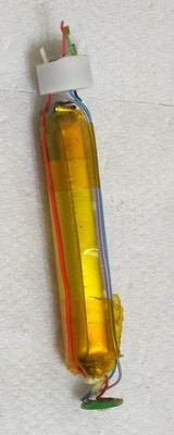 |
 The easiest way to get a circuit is to remove one from an old battery. You will need an old batttery and an old atty. Instead of throwing them away, screw the atty to the battery and grip both ends with either pliers,spanners or two pieces of hollow pipe. By slightly bending and rotating about the joint, you will be able to slowly pry the socket away from the battery. The other end of the battery is usually easier, just remove the plastic stopper with a pair of pliers. With the two-ends gone, push a sturdy thin rod through the hollow at the end without the circuit. The contents should come out the other end. |
 |
| Know the Circuit | |
|
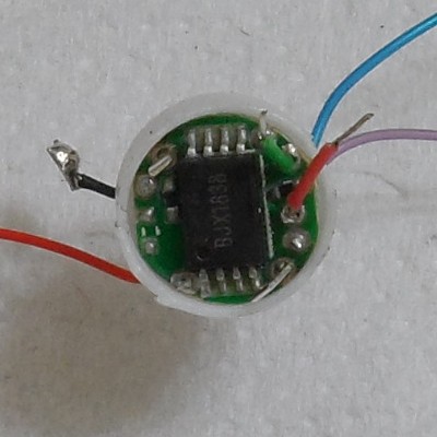
The wires you
need to find are; 1. input power wires; red = +ve in
2. switcher wires
(un-coloured)black = -ve ground Connect these to the mod battery. These 2 points trigger on the power
when met. They are usually at diagonal corners of the circuit
board and also act as legs for the sensor. (We don't need the
sensor, it's been ripped off in the pic.)
Connect these two to your mod switch. 3. output power wires red = +ve out
green = -ve out These two connect to your atomiser. and optionally,, 4. led indicators you don't need these unless you
also want to add fancy led lights to your mod. Usually the blue one
is for the green led and the purple is for the red led.
|
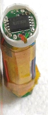
 A typical circuit off a 'mini' style battery. Limits the upper voltage to around 3.7v. |
| Test the circuit | |
|
I'd advise you to give the
circuit a test with a multi-meter before you solder into the
mod. Connect to a battery, activate the switch wires and measure the voltage off the out wires. You should get 3.7v even if the battery is at 4.2v Note that some circuits are not designed to limit the voltage, so you'll have to throw it away and find one that does. Also some circuits auto-cut-off if the current is too high, so test with an LR atomiser if you intend to use one. |
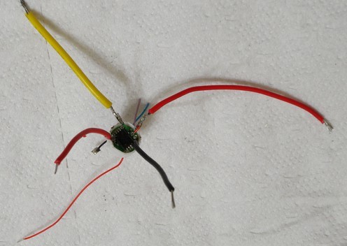 |
| (green replaced with yellow wire here, and two switcher wires added red,black) |
| Wire it in |
|
|
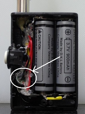
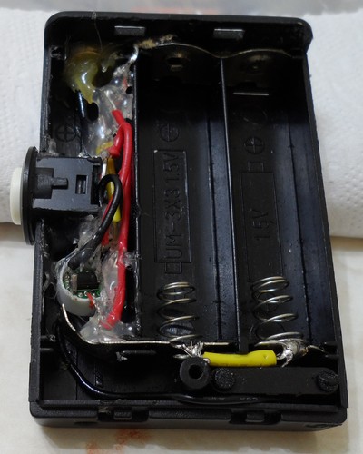
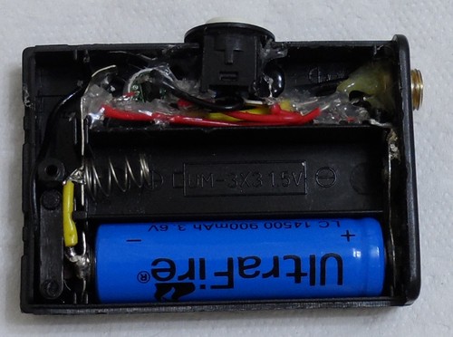
There's plenty of room in the
box for the circuit. |
 |
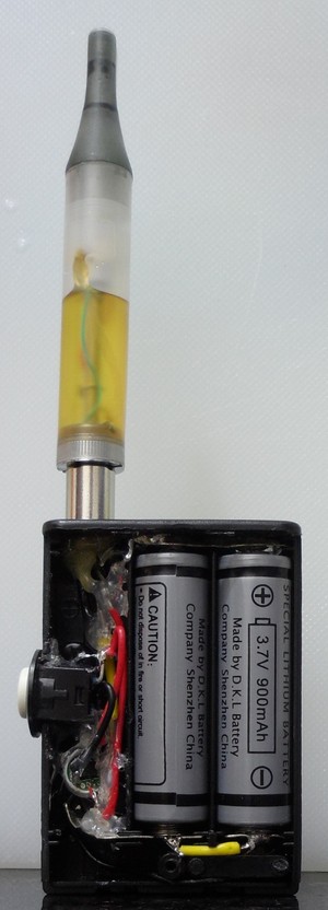
| Then you can give it a final test. |
 |
That's It !
 |
 |
Enjoy a smoother consistent vape with no over-burning or sore tongue problems and squeeze the most of that flavour from your favorite e-liquid.